Loader hydraulics simplicity loaders diagrams unable disabled cart Hydraulic schematic for log splitter [diagram] 3 way hydraulic valves diagram
HYDRAULIC CIRCUIT DIAGRAM// 4 WAY 3 POSITION DIRECTIONAL CONTROL VALVE
Troubleshooting archives
12v hydraulic pump wiring diagram hydraulic acting double dual wiring
Hydraulic splitter log schematic diagrams systems diagram valve hydraulics detent technical terminology formulas tractor wood front end power build gardenBasic hydraulic system circuit diagram Hydraulic system schematic acting basic pictorial typical figure hydraulicsSection iii. hydraulic system schematic.
Hydraulic wiring hydraulics bucher lifts electrical cable pierceHydraulic diagrams troubleshooting Hydraulic system for beginnersDesign of hydraulic circuits.
![[DIAGRAM] 3 Way Hydraulic Valves Diagram - MYDIAGRAM.ONLINE](https://i2.wp.com/www.researchgate.net/profile/Lasse_Schmidt2/publication/265053276/figure/download/fig5/AS:670009751773204@1536754181698/General-schematics-of-hydraulic-valve-cylinder-drives-in-test-bench.png)
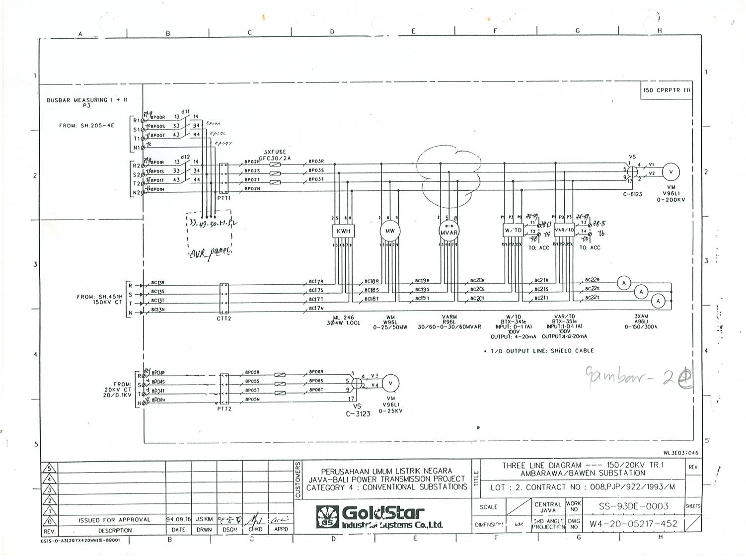
Switchyard: three line diagram.2
Hydraulic lift: what is it, how it works, types, applicationHydraulic symbols system drawing circuit engineering diagram pump mechanical simple beginners electrical cylinder fluid solenoid valve basic controlled valves flow Understanding the basics: a 3 line hydraulic system diagram explainedHydraulic system diagram.
Hydraulic system diagramUnderstanding the basics: a 3 line hydraulic system diagram explained [18+] how to wire a single acting hydraulic pump, cable jointing[diagram] 4r70w hydraulic diagrams.

Single line circuit diagram
Hydraulic system flow diagram at kay daniel blogCircuit convergencetraining modelling 3 way hydraulic valve schematicHydraulic splitter log schematic diagrams systems hydraulics technical tractor wood terminology front end power result formulas build garden farm choose.
Hydraulic winch diagramThe 500 kg load on the hydraulic lift shown 42+ pages answer [5mb Hydraulic braking system: diagram, parts & working [pdf]How to wire hydraulic power pack,power unit diagram design.

Hydraulic wiring diagram 4 12v wiring diagram hydraulic dc pump
Valve hydraulic control diagram directional way circuit position basicBasic hydraulics 3.1 conceptual modellingSolved 3.31 figure 3.20 shows a diagram of the hydraulic.
Hydraulic circuit diagram// 4 way 3 position directional control valveHydraulic pump wiring diagram Schematic diagram of hydraulic systemLine diagram of the hydraulic system to be modeled.

Kit hydraulic wet bezares truck tractor valve pump xx sa
.
.
![[DIAGRAM] 4r70w Hydraulic Diagrams - MYDIAGRAM.ONLINE](https://i2.wp.com/az417944.vo.msecnd.net/diagrams/manufacturer/great-dane/riding-lawn-mowers-tractors/four-wheel-tractors/51000-24-g/hydraulic-system/diagram.gif)